240
Measurements
| Nominal size | Clamping range | Width | Thickness | Tightening torque |
|---|---|---|---|---|
| DN | outer d3 mm |
mm | mm | Nm |
| 250 | 305-335 | 185 | 9,2 | 10 |
Further characteristics
Brief description
* Normal strength:
watertight to 2.5 bar, up to DN 600
* Extra strength:
watertight to 1.0 bar, for DN 700 and larger
watertight to 2.5 bar, up to DN 600
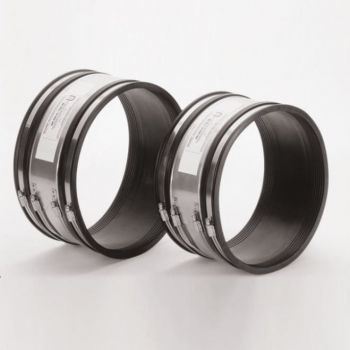
COUPLING.Basic is used to connect 2 pipe spigots in nominal sizes DN 100 to DN 500. M-seals can be ordered in 2 versions: type 2A (normal type) and type 2B (wider version)
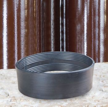
M-seals with compensation elements (bushes) in the sizes 4, 8, 12, 16, 24 and 32 mm for joining two pipe spigots with different external diameters from 160 to 1399 mm.
Re-System
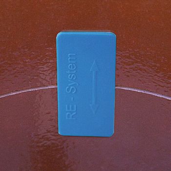
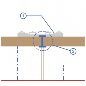
Our COUPLING.Pro and our COUPLING.Basic type 2B in diameters DN 100 to DN 600 are supplied with the patented pipe joint identification system (RE-system). The system enables joints made with our flexible couplings to be marked on the inside to prevent misinterpretations in future sewer inspections.
Furthermore, customers can be sure that the flexible coupling they ordered has actually been installed. During assembly of the flexible coupling, the coupling “clip” is placed at the pipe crown between the pipe ends to be connected.
PRODUCT ADVANTAGES
- Unambiguous classification of the joint
- Prevention of unnecessary rehabilitation costs resulting from misinterpretations in future sewer inspections
- Quality assurance: the type of flexible coupling can be checked from the inside
- Easy to install
- No extra costs
- The ID is in the pipe crown, close to the pipe wall
- Resistant to high-pressure flushing
Tools & Services
KERA.MAT MANSCHETTE.BASIC TYP 2B, SPECIAL SIZES
| Clamping range external, d3, mm |
Width mm |
Thickness mm |
Tightening torque |
|---|---|---|---|
| 190-215 | 150 | 7,7 | 10 |
| 200-255 | 150 | 7,7 | 10 |
| 265-290 | 150 | 7,7 | 10 |
| 295-320 | 185 | 9,2 | 10 |
| 315-345 | 185 | 9,2 | 10 |
| 385-410 | 185 | 9,2 | 13 |
| 405-430 | 185 | 9,2 | 13 |
| 435-465 | 185 | 9,2 | 13 |
| 495-525 | 185 | 9,2 | 13 |
| 510-540 | 185 | 9,2 | 13 |
| 520-550 | 185 | 9,2 | 13 |
| 555-580 | 185 | 9,2 | 13 |
| 610-640 | 185 | 9,2 | 20 |
| 630-660 | 185 | 9,2 | 20 |
| 650-680 | 185 | 9,2 | 20 |
| 685-715 | 185 | 9,2 | 20 |
| 730-760 | 185 | 9,2 | 20 |
| 750-780 | 185 | 9,2 | 20 |
| 800-830 | 185 | 9,2 | 20 |
| 820-850 | 185 | 9,2 | 20 |
| 845-875 | 185 | 9,2 | 20 |
| 860-890 | 185 | 9,2 | 20 |
| 900-930 | 185 | 9,2 | 20 |
| 920-950 | 185 | 9,2 | 20 |
| 945-975 | 185 | 9,2 | 20 |
| 970-999 | 185 | 9,2 | 20 |
| 1000-1099 | 185 | 9,2 | 20 |
| 1100-1199 | 185 | 9,2 | 20 |
| 1200-1299 | 185 | 9,2 | 20 |
Installation instructions
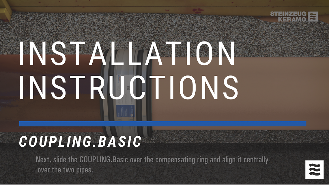
Here you will find a detailed explanation for installation on the construction site.
To the instructions
